Instead of expensive, special purpose roll grinder, We are offering an economical and effective solution to cover a wide range of roil crown grinding.
| |||||||||||||
 | Suitable for
| ||||||||||||
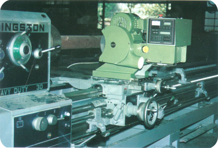
Turning tool holder equipped, good for massive pre-grinding cutting, and followed by grinding process within the same chucking. Crown curve turning can be applied to some roll materials which turning may be a better solution than grinding. Low speed ranges are designed for vitrified grinding wheels which cover a wide range of materials with perfect surface finishing.
|  | ||||||||||||
|
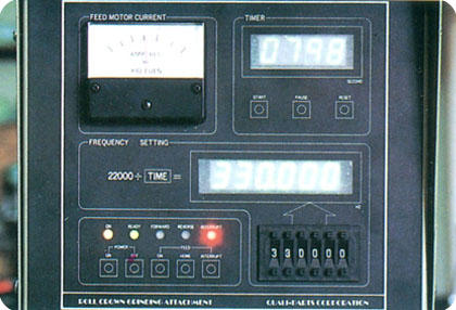
| Advanced electro-mechanical control system and stepping motor generate um base continuous path control over the entire grinding process. •good geometric accuracy •good symentric profile •good surface quality •reproducible profile Easy operation, a basic lathe operator can learn to operate the machine within an hour. Cartridge designed control unit to be replaced as a single unit to minimize service down time.
| ||||||||||||
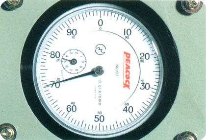
Built-in 0.01mm/0.0005” dial gauge to measure the Actual diameter variation during crown grinding Process. Roll camber (crown height) can be adjusted by hand wheel.
|
| ||||||||||||
|
|
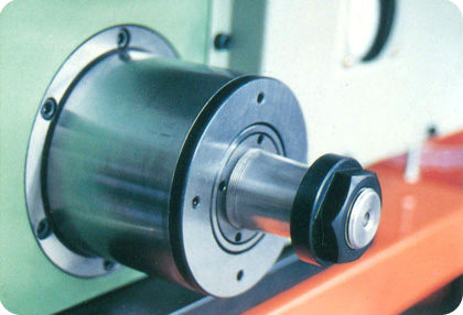
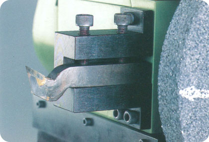
| Precision Balanced, Dust Tight, and manintenance-free grinding spindle with oven-sized design, covers a wide range of grinding requirements with a long service life. Lowest vibration level and perfect concentricity to achieve the finest surface finish to save polishing time.
| |||||||||||
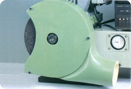
Aluminium alloy protective guard
when the load exceeds design safety factor.
|
| ||||||||||||
Support pillars must be sized that center line of work piece and center line of grinding wheel are exactly on the same plane. | |||||||||||||
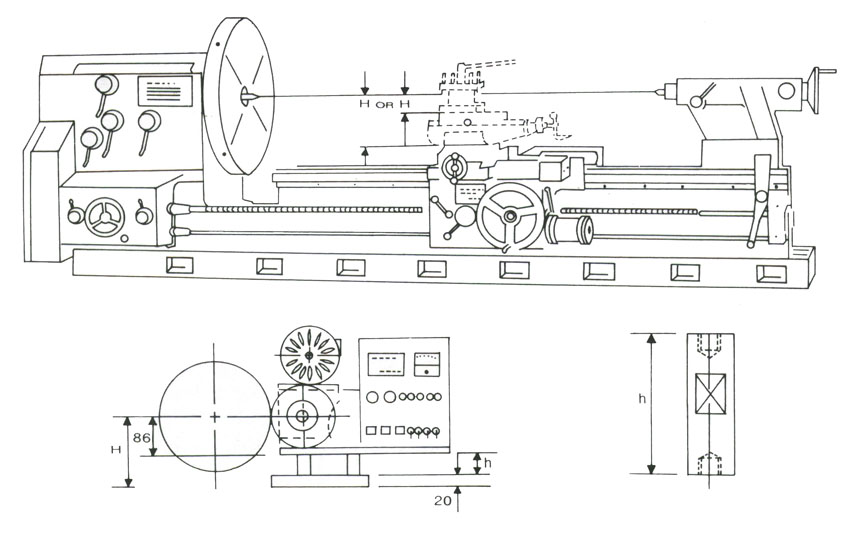 | |||||||||||||
The length of support pillars can be calculated by following formula H = h+106 mm H = The height between center line of lathe to the top of the cross—slide h = The length of support pillar The grinding attachment can be mounted on any lathe with H ≧ 86mm | |||||||||||||
|
| |||||||||||||